The sawn timber and logging sections of this code include the relevant parts of the Ministry of Business, Innovation, and Employment codes, which have been based on a joint industry and government department group research and proven safety needs. The style of this section is slightly different from the rest of the code as it has been written by the Ministry of Business, Innovation, and Employment. Some sections that are not relevant to road transport have been omitted.
Refer to the Log Transport Safety Council Log load securing requirements.
Log transport safety council - Industry standards(external link)
For more information contact:
The Secretary
Log Transport Safety Council
127 Balmoral Drive
Tokoroa 3420
Email: ltsc@logtruck.co.nz
Website: www.logtruck.co.nz(external link)
Increasing amounts of timber are being transported on public highways on vehicles which are constantly increasing in size and payload capacity. Government and industry are concerned at the number of fatal and serious accidents involving the collapse of timber stacks and the spillage of loads of timber in transport.
This section has been prepared following several years of research and investigations, plus extensive tests, to publicise what has been proven to be the safest and most correct methods of securing timber on vehicles in preparation for transportation.
The tests and investigations have also shown the need for correct design requirements for the vehicles and restraint equipment, as well as minimum standard methods for securing a load on a vehicle.
Any load carried on a vehicle must be sufficiently restrained to prevent movement from forces which arise from the vehicle passing over road undulations, when it changes direction, or when it is being braked or accelerated.
The forces involved in restraining the load in braking depend on the deceleration and the weight of the load, and are not dependent on the speed of the vehicle. If, however, a load does move at high speed, it will have more energy and hence it will cause more damage.
It requires much more force to stop a load which has started moving than it does to prevent the movement in the first place. It is essential, therefore, that the vehicle is loaded and the load restrained in such a way that no part of the load can freely move in any direction.
The total restraint required to accommodate the forces which arise will generally be obtained from a combination of the following:
A load carried on a vehicle without restraining devices will not be secure because the frictional restraint between the load and the platform of the vehicle will be less than the dynamic forces which tend to move the load. It follows, therefore, that it is necessary to provide additional restraint to prevent the load moving.
The load restraint system must be capable of preventing movement of the load under three particular conditions (see figure 47):
 Figure 47 Payload forces
The load restraint system must be able to withstand:
In certain circumstances, vertical acceleration may occur but this will be overcome if the restraints mentioned above are imposed by lashings placed over the load.
In addition to meeting the statutory requirements applicable to the construction, equipment and loading of motor vehicles, the vehicle’s load space and the condition of the platform must be suitable for the type and size of the load to be carried. The manufacturer’s gross vehicle weight must not be exceeded; nor should the individual axle weight be exceeded.
Unless the requirements for packages loaded without a headboard are fully met, either a headboard or cab guard must be fitted between the load and the cab.
Requirements for packages without headboard
The following is specifically related to transportation using securing devices and an open loading platform. Any other load restraint system must be certified by a person approved to undertake certification in accordance with NZS 5444 Load anchorage points for vehicles.
A minimum of two securing devices must be used to secure each section of load. When a third device is required, it should be passed over the lower half of the load only. Subsequent devices should be over the complete load.
Care must be taken to ensure that the securing devices are placed at points where the load is rigid, extending over the load to anchor points opposite each other.
Securing devices should be tightened at the start of a journey, checked after a few kilometres of travel, and then rechecked during the course of the journey as the timber settles on the vehicle. Steel corners help to protect the load and reduce slackening as the securing device cuts into the timber.
Uneven ends should, where possible, be at the rear of the vehicle. Any loose ends of timber should be secured, pulling them together to minimise whip.
When packets are not the total width of the truck deck, spacers should be placed in the centre of the load to extend the load widthways to get maximum effect from the securing system and minimise sideways movement of the load.
A slippery platform surface is always dangerous. The aim should be to obtain the maximum advantage from frictional restraint by keeping both the base of the load and the platform surface as clean, dry and free from grease as possible.
When the load is wrapped, timber bearers should be used to minimise movement on steel decks.
A headboard, when fitted to the front of the platform of a vehicle, must be capable of withstanding a horizontal force uniformly distributed over the vertical area, equal to half the rated payload capacity of the vehicle. Where possible, the load should be placed tightly against the headboards. If this is not possible, additional packing or chocks should be placed between the load and the headboard.
The headboard should meet with the following requirements:
A cab guard must be designed to protect the driver in the event of a rollover and also to absorb the impact of a load moving forward.
Sideboards and tail gates, when fitted to the rear or the side of the vehicle platform and used as load restraint equipment, must be capable of withstanding a horizontal force uniformly distributed over the vertical area. The force must be equal to half the total payload weight.
Side and centre posts, when fitted and used as load restraint equipment, must be capable of withstanding a horizontal force uniformly distributed over the vertical area. As above, the force should be equal to half the total payload weight. Side posts must be arranged or braced so that the width of the vehicle when laden does not exceed legal limits. All posts must be designed so that they cannot inadvertently become detached from the holders.
Load anchorage points must comply with the requirements of NZS 5444 Load anchorage points for vehicles. The number of anchorage points fitted and used and their strength must be equal to the securing device being used, and should be at least as strong as the securing device. For example, if two 5-tonne-rated strength securing devices are used, the four anchor points must each have a strength of 5 tonnes.
The securing device and the tensioning device must be maintained in a sound condition. Over-tensioning should be avoided as this could overload the system and weaken it.
Sheets or tarpaulins should be regarded as providing no more than weather protection. The load must be independently restrained against movement.
Sisal and manila ropes should be used only for securing tarpaulins or loads of less than 0.5 tonne. These ropes are easily damaged and constant examination is required to ensure they are serviceable.
Other ropes should comply with AS/NZS 4345. Preferred ropes are of polypropylene, polyester or polyamide manufacture.
When purchasing, the buyer should ensure the supplier gives written information about the ropes and the standards to which they have been made. This would include the types of material and construction, the minimum breaking force and the standard number.
Avoid contact with chemicals, oils and paints. Provide a suitable box for storage. To extend the rope’s life, coil with the lay and avoid excessive knotting, sharp bends, chafing and passing over sharp or rough edges.
Regular detailed examination for wear and mechanical damage should be carried out. If there is any doubt about the ability of the rope to perform safely, it should be withdrawn from service.
All chains must be of short link and comply with AS/NZS 4344 or BS 4942. Tensioning devices and fittings, which must be identified with manufacturer’s identity and rated load, must be compatible in size and strength with the chain to which they are attached. All manufacturers and importers of tensioning devices and fittings to be used with such chain must ensure that components carry an SWL identification.
The following safety precautions must be taken when using and inspecting chains:
Claw hooks are preferable to grab hooks, as grab hooks reduce chain strength by approximately 25 percent.
All webbing load restraint assemblies must comply with AS/NZS 4380.
Webbings, winches and fittings must be maintained in good condition and used in accordance with the manufacturer’s instructions. Webbing must be replaced if there is any sign of damage, chafing, fraying or stitching failure. Fittings, winches, etc must be replaced if bent, worn or faulty and must not be repaired by welding.
The methods used for stacking and packeting timber depends on its end use and destination. Large quantities of timber are fillet stacked for both kiln and air drying. Under normal conditions, timber for air drying can remain for up to one year in this state. When kiln drying, the period is usually of shorter duration. When timber is to be stacked for any considerable period of time, the stacks must be monitored by the yard proprietor or designated agent to ensure their continued stability.
 Figure 48 Parts of a timber stack
The movement and stacking of timber must be carried out in accordance with the approved code of practise.
Particular attention should be paid to section 5.5 of Safety code no. 1, which states:
‘Only carry loads that are supported by their carriage or backrest extension.’
Figure 48 illustrates the parts of a timber stack. The rule is the height is to be no more than four times the width of the base. If it is intended to exceed this, a tie is required.
Before allowing stacks to be constructed in the open, a check must be made by the yard proprietor or designated agent to determine if the ground is firm enough to support any load expected to be placed there. The existence of drains, water pipes or electric supply mains under the proposed site must be ascertained. Manholes, stop valves, cable chambers and fire hydrants must not be built over. When timber is stacked adjacent to a boundary where there is public access, the stacks should be end on, at least 1 metre from the boundary. Alternatively, if stacked side on to the boundary, then restraining devices of calculated strength must be provided to the full height of the stack.
The site for timber stacks should be selected for its ground stability, level and even contour, and its accessibility for whatever method is used to pile or unpile the stacks, for instance forklifts, side-loaders, hand stacking.
Solid foundations must be provided, otherwise the stack will be faulty from the start. The following types of foundation are acceptable:
Stack bearers or foundations should be placed as evenly as possible, and must be of an appropriate strength and size for the weight of the timber likely to be supported and to prevent sagging of the base packet.
Stacks should not be located too close to live power lines. You must ensure that machines which work the stacks are no closer than 4 metres to any live power lines.
Even a relatively light wind can dislodge timber from a stack in the open. The timber often has sufficient weight and falls far enough to kill or cause serious injury.
Upper layers of stacks exposed to high winds should be restrained to prevent dislodgement. Generally, stacks should slope slightly along their length so that rain water will run off.
While tarpaulins can be used to protect timber from the weather, they should not be used as a means of securing the stack.
The key to good stack building lies in the use of fillets, which tie adjacent pieces together by friction. Those used to stabilise block-stacked packets are called binder fillets. Those used to separate timber for drying are separation fillets.
Ties are equally important with stacks of packaged timber in that they stabilise adjacent packages and stacks.
Staggered plank ends protruding from stacks encourage people to use them for climbing and should be avoided where practicable.
No one should climb up the side or ends of any timber stack. A ladder should be used to facilitate stocktaking. Where a forklift is used for this purpose, a proper working platform must be provided.
All timber should be filleted and stacked with its greater dimension on the flat, and all fillets must be of even thickness.
Fillets and spacers should be long enough for the width of the stack. Should shorter ones need to be used, they must not be placed end to end but must overlap each other so that at least two tiers of timber are supported on each side of the overlap.
Wherever possible, fillets should not be left protruding more than 50mm beyond the edges of a stack to prevent danger to passersby.
Fillets must be placed immediately above each other and also in relation to the stack bearers. In general, the narrower the dimension of the timber, the wider and/or more closely spaced the fillets should be. They should never be placed over 1 metre apart.
When complete packets are piled one on the other, any irregularity or unevenness such as sagging ends must be corrected by packing with spacers that are placed between the packets.
The major cause of timber spillage has been the collapse of the base of the packets, where extreme force has been imposed on the load restraint devices. As all types of packet binders are tensioned from the top and do not effectively consolidate the base, it is extremely important that when packets are being assembled and bound, the bottom layers are mauled up tightly.
The use and placement of binder fillets are important factors in creating a stable packet. Generally, they should never be more than 1 metre apart along the length of the packet. However, where an automated fillet system is used, a maximum spacing of 1.2 metres is allowable. Details of fillet position for various dimensions of timber are shown in figures 49, 50, 51 and 52.
As with filleting timber, packeting timber spaces should be long enough and should not protrude more than 50mm beyond the packet. The packets should be placed immediately above each other in relation to stack bearers.
All timber is to be packeted with its greater dimension on the flat.
Packets of random-length timber should be formed so that the short lengths are securely housed within the body of the packet. All outside pieces must engage all of the fillets. Where short lengths are butted, extra care must be taken to ensure that they remain secure.
All packets of block-stacked timber must be suitably bound at a point as near as possible to where they have been assembled. For transporting short distances on level ground about a timber yard to treatment plants, planing sheds or filleting bays, it is not considered necessary to bind the packets as effectively as for when they are to be transported greater distances and on public roads.
All binders must be set square to the packet. Some packets will need to be rebound after drying, etc should binders be found to have lost their tension.
Packets to be transported must be tightly put together, particularly at the base, and must be bound with at least two strategically placed binders of equal or greater strength than 10-gauge 3.2 high-tensile wire, with a breaking strain of 661kg, suitably tensioned and secured.
Packets must be constructed and bound so they are able to withstand a horizontal acceleration equivalent to half the weight of the packet. If there is any doubt concerning this capability, then a simple tilt test can be carried out. The packet should be able to withstand a sideways tilt angle of at least 26° before showing signs of any significant distortion.
Generally, block stacking consists of placing packets of timber already prepared one on the other.
Because fewer fillets are used to provide binding of the stack and to compensate for irregularities, block stacking must never be higher than four times the width of the base. Where narrow packets are involved, they can be bound together to make one packet and then be stacked to four times the base width. This will help to retain storage capacity.
However, in storage sheds or where overhead cranes are used, packets can be stacked to 9.7 metres, provided a method of ensuring stability is used.
Packets stacked must be compatible in size and structure. Packets of long length timber must not be stacked on top of single short-length packets. Any sag in packets should be corrected by the packing of the spacers between the packets.
If more than one person is concerned in this operation, only one should be responsible for the manner in which the stack is reduced.
Binders must not be cut unless everyone is in a position of safety in case any part of the stack collapses or part of the binder flies back.
Binders must not be cut by any person standing on a stack unless it is adequately supported on both sides.
If it seems apparent that any part of a stack or packet will collapse when the binder is cut, the packet must be suitably stayed or held together by a forklift or other means.
The packet should be taken down layer by layer rather than tier by tier ensuring that the remaining part is in a safe condition.
Fillets, spacers, wires and straps, etc should not be left lying about as a tripping hazard.
Maximum sizes of packets for transportation are shown in figures 49–52.
 Figure 49 A typical packet of timber
  Figure 50 Placement of fillets for timber width less than 76mm
Figure 51 Placement of fillets for timber between 76mm and 125mm
 Figure 52 Placement of fillets for timber width greater than 125mm
It is difficult to identify all the different types and sizes of product under this title so it is understood that, in all cases, the spirit and intention of the preceding items in this code is followed by all concerned. Some of the more usual products are dealt with in the following paragraphs.
The sizes of export packets of timber are determined by shipping and the requirements of the overseas buyer. These are too numerous to describe, however the spirit of sound packaging as set out on in binding packets applies.
Sound packaging - binding packets
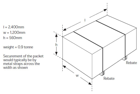
Typical sheet wood products like plywood, particle board, veneer boards and hardboard, for example, are usually 2400 × 1200 (some at 3600 × 1800).
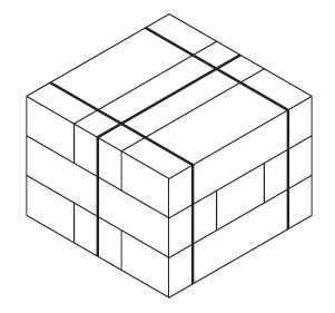
Figures 53 and 54 are typical examples of a small packet and a large packet.
 Figure 53 Typical small packet
 Figure 54 Typical large packet
Figure 55 Cross stacking and interlocking
Decorative boards that are slippery by nature should be encased in 7.5mm plywood or shrunken heavy-duty polythene before being secured with straps or wire. For convenience and minimal damage, bearers may be incorporated with the packet.
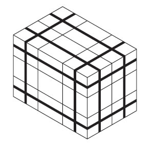
Small-piece timber must be packeted so that under normal circumstances stacks and packets are self-supporting. Full use of cross-stacking and interlocking techniques should be made (see figure 55). Some packets may need binding in three directions (see figure 56).

Figure 56 Three-dimensional binding
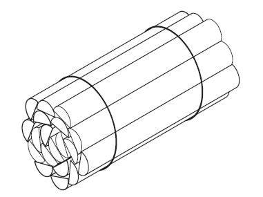
 Figure 57 Half-round posts
Packets of timber meeting the timber stacking and packeting requirements, which are to be transported on a vehicle platform, must be secured by securing devices which pass from the deck on one side of the vehicle over the load to the anchor point on the other side of the deck.
Timber stacking and packeting requirements
For packets which are not loaded against a headboard, the securing devices must have a combined rated strength of at least twice the weight secured, eg a 10 tonne payload will require two chains, each having a rated strength of 10 tonnes (see figure 58).
For packets which are loaded against a headboard so that the tops are supported by at least 150mm, the securing devices must have a combined rated strength of at least the payload secured, eg a 10 tonne payload will require two chains each having a rated strength of 5 tonnes (see figure 59).
Restraint equipment - headboards
For packets which are loaded so that the lower packets are supported by a headboard, but the upper packets are not supported, must be secured by securing devices, having a combined strength of at least 1.5 times the payload secured, eg a 10 tonne payload will require two chains each having a rated strength of 7.5 tonnes (see figure 60).
Restraint equipment - headboards
Timber or other timber products, which are not packaged according to the timber stacking and packeting requirements, must be transported as if they were packeted timber. However, suitable centre or side posts must also be used.
Timber stacking and packeting requirements
8mm grade P chain rated strength = 5.12 tonnes
10mm grade P chain rated strength = 8.0 tonnes
8mm PWB Hi-65 chain rated strength = 7.1 tonnes
If the load is against the headboard, chains of 10 tonne rated strength are required. For example:
If the load is not against the headboard, chains of 20 tonne rated strength are required:

Figure 58 Packets not loaded against a headboard

Figure 59 Packets loaded against a headboard

Figure 60 Bottom packets against headboard but upper packet not secured

Figure 61 Method of securing with three chains
In all circumstances the driver of any truck and trailer carrying sawn timber has the final responsibility to ensure that the truck is loaded correctly. The driver is responsible for the correct securing of the load in accordance with this code and the approved code of practice (in particular parts 16 and 17).
Approved code of practice for safety and health in forest operations(external link)