The reason for assigning an asset an RP is to ensure that it can be easily located using its RP in subsequent inspections, Inventory Surveys, etc.
The true definition of RP for a culvert that passes under the road on an angle is where the centreline of the road passes through the centreline of the culvert (see below). However, this can make it difficult to locate the inlet and outlet as they can occur some distance either side of this RP (most culvert inspections focus on condition of inlet and outlet).
Use the RP of the LHS inlet/outlet. This ensures that the culvert LHS inlet can be easily located without crossing the road. The location of the RHS Inlet can be determined once the LHS Inlet is located.
Figure 1: Measuring RP for Angled Culverts

The offset for sumps (or any single point displacement asset) located on the island of a Divided Median Highway are measured from the centre of the increasing or decreasing section, not the centre of the island. Therefore if the increasing direction is 7m wide (2 lanes) and there is a sump on the RHS (ie on the island) then the offset is 3.5m and the side is right.
However, the offset for a sump (or any single point displacement asset) located on the island of a decreasing section of Divided Median Highway has an offset of 3.5m and is on the left.
Offset should be measured to the nearest 0.1m. As long as the drainage asset can easily be located using the offset provided then that is adequate. For offset drainage items that move water away from the road (ie flumes and side culverts), the offset should be the distance from the centre of the road to the nearest point of the asset to the road centreline.
Figure 2: Culverts with differing offset

Complex drainage systems like the example below can be captured by recording 3 culvert assets at the same displacement. There will be one culvert and two side culverts (one on either side of the road). This way you can record the lengths and diameters of each culvert individually, as they are most likely to be different. Use a similar method for recording culverts with flumes, slot channels, etc at culvert ends.
Figure 3: Recording multiple drainage facilities

SWC offset is the distance from the edge of seal to the invert of the surface water channel. Lined SWC (eg Kerb and Channel) has an offset of 0 and earth surface water channel can have an offset ranging from 0.5m to 10.0m, with the exception of kerb and channel.
Use the 'Offset' field to determine SWC’s that are close to the road and those that are further away from the road, in the unlikely event when there are two channels running beside the road.
Collecting the data for earth surface water channels is very subjective (note that this does not include lined surface water channels). Apply the following limits of variation:
Record lined SWC on major islands only, eg where there are sumps. Typically there is no Channel associated with lined SWC on islands so ensure you use the correct code (MKC, KC, etc).
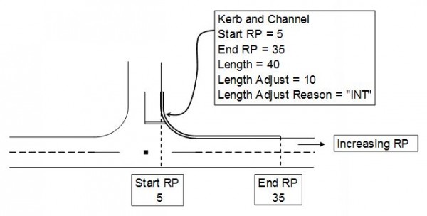
'Length Adjust' and 'Length Adjust Reason' are only used when the length of the SWC asset is not equal to the End RP less the Start RP. The following diagram shows an SWC requiring length adjustment.
Figure 4: Length adjustment for kerb and channel
For further information contact HNOperformance@nzta.govt.nz.